Chapter 2. Creating a VC Scene
This chapter explains how to build a VC scene. It is divided into six sections and gives an overview of all the kinds of markup that are possible in VC scene descriptions. The information here is intentionally schematic; details are given in the reference chapters of this documentation (Chapter 5 and Chapter 7). The first section presents the structure of a VC scene through node hierarchy together with transformations. The second section introduces the media objects: geometric primitives, lights, viewpoints, and crowds that can have graphic and sonic properties. In the third section, interpolators are presented in relation with transformations and objects on which they operate. In Section 2.4, routing and script writing are described. Macro-Commands for algorithmic scene descriptions are presented in Section 2.5. Last, Section 2.6.1 and Section 2.6.2 describes the selection and dragging mechanisms used in VC. [1]
2.1. Scene Graph Structure
A VC scene is described in an XML syntax. The grammar of VC will be described with RelaxNG in future version of the documentation. As any XML document, the first line of a VC file must be:
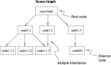
<?xml version="1.0" encoding="utf-8"?>A VC scene is hierarchical. There is a unique root node that contains sub-nodes called daughter nodes. These nodes contain in turn (recursively) other nodes that build the graph structure. The structure is said to be directed because the connection between nodes and sub-nodes is oriented, and acyclic because a node cannot be its own descendant. The structure however allows multiple inheritance because a node can have more than one parent node.
The following example shows a scene graph structure built through node hierarchy. <xref> markups can be used as cross-reference to another part of the document, or to parts of documents on the same URL. Figure 2-1 illustrates the graph built from this node hierarchy.
<?xml version="1.0" encoding="utf-8"?>
<node id="mainNode">
    <node id="node1.1">
        <node id="node1.1.1">
        </node>
        <node id="node1.1.2">
        </node>
        <node id="node1.1.3">
        <node>
    </node>
    <node id="node1.2">
        <use xlink:href="#node1.1.3"/>
    </node>
    <node id="node1.3">
        <use xlink:href="bib/P1/house.xml:#nodeH1"/>
    </node>
</node>
2.1.1. Transformations Associated with Structure Nodes
According to the hierarchical structure, structure nodes divide into two categories: non-terminal nodes that have at least one daughter node and leaf nodes without descendant. Each non-terminal node can possibly carry a geometrical transformation: a rotation, a quaternion, a translation, a scale, a circle transformation, a ellipse transformation, a spiral transformation, or a path transformation.
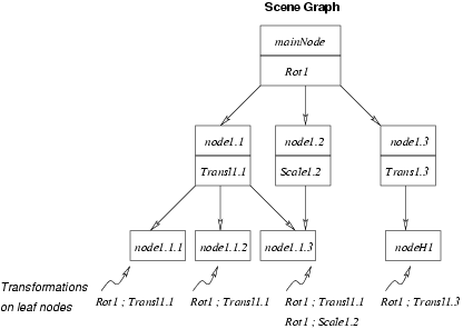
In a scene graph, each transformation applies to all the sub-nodes of the current node. Thus each node N is transformed by the composition of the transformations encountered along the path that leads from the root node to N. In case of multiple inheritance, a node N with p paths from the root node is rendered p times. Each rendering is associated with the composition of the transformations associated with the pth path.
The following example shows the graph structure of Figure 2-1 complemented with transformations. Figure 2-2 shows the resulting transformations on each leaf node. Node node1.1.3 is rendered twice with two different transformations.
<?xml version="1.0" encoding="utf-8"?>
<node id="mainNode">
    <transformation id="Rot1"
      geometry="rotation" x="0.0" y="0.0" z="1.0" angle="30.0" />
    <node id="node1.1">
        <transformation id="Transl1.1"
          geometry="translation" x="3.0" y="-1.2" z="1.0" />
       <node id="node1.1.1">
        </node>
        <node id="node1.1.2">
        </node>
        <node id="node1.1.3">
        <node>
    </node>
    <node id="node1.2">
        <transformation id="Scale1.2"
          geometry="scale" x="2.0" y="2.0" z="1.0" />
        <use xlink:href="#node1.1.3"/>
    </node>
    <node id="node1.3">
        <transformation id="Transl1.3"
          geometry="translation" x="8.2" y="0.0" z="0.0" />
        <use xlink:href="bib/P1/house.xml:#nodeH1"/>
    </node>
</node>

